Router on a stick configuration
Router on a stick configuration is used for "routing packets between VLANs". According with Cisco official Cert Guide, the Router-on-a-stick configuration describes a concept as "Routing Layer 3 packets between Layer 3 subnets, with those subnets each mapping to a different Layer 2 VLAN".
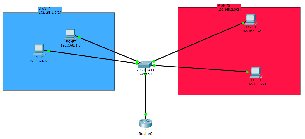
This configuration is pretty simple to set. You can choose to test it using Packet Tracer or using a CCENT/CCNA Home Lab. About the second choice you need at least 2 End devices, a LAN switch, a router and 3 ethernet cables. Personally, I used this configuration: Cisco Router 2611, switch Catalyst WS-C2950G-24-EI, Raspberry and PC.
Firstly, we must create two, or more, VLANs and assign some interfaces. About the switch configuration, this are the commands:
Switch#configure terminal
//Next command configure a range of interfaces, I include 0/1 and 0/2 because
//on Packet Tracer I set 2 end devices for each VLAN. On the Home Lab I attached
//only a PC on fastEthernet 0/1 in Vlan1 and Raspberry on 0/2 in Vlan2
Switch(config)#interface range fastEthernet 0/1 - 2
//Next command sets the mode for the interfaces 0/1 and 0/2
Switch(config-if-range)#switchport mode access
Switch(config-if-range)#switchport access vlan 10
% Access VLAN does not exist. Creating vlan 10
Switch(config-if-range)#exit
Switch(config)#interface range fastEthernet 0/3 - 4
Switch(config-if-range)#switchport mode access
Switch(config-if-range)#switchport access vlan 20
% Access VLAN does not exist. Creating vlan 20
//Next command is about the interface attached to Router
//(I used a gigabitEthernet interface) and sets the trunk Operational Mode.
//Note that the Operation Mode is different from the Administrative Mode.
//You can set 3 differents Administrative Modes, which will set a trunk Operation Mode:
//Trunk, Dynamic Auto, Dynamic Desirable. Only Trunk Administrative mode set a trunk
//Operational mode, about the 2 other modes depends on the configuration setted on the other side.
Switch(config)#interface gigabitEthernet 0/1
Switch(config-if)#switchport mode trunk
Switch(config-if)#end
Switch#copy running-configuration startup-configuration
Destination filename [startup-config]?
Building configuration...
[OK]
Secondly we must configure an interface on the Router that will use as truning interface:
Router(config)#interface gigabitEthernet 0/0
Router(config-if)#no shutdown
Router(config-if)#interface gigabitEthernet 0/0.1
//Now we are in the subInterface section and we set the VLAN which the subinterface belong to
Router(config-subif)#encapsulation dot1Q "VLAN ID"
Router(config)#interface gigabitEthernet 0/0.2
Router(config-subif)#encapsulation dot1Q "Second VLAN ID"
Router#copy running-configuration startup-configuration
Destination filename [startup-config]?
Building configuration...
[OK]
Now just assign a valid IP to each end Devices, based on the VLAN which belong to. You can download this example that I made on Packet Tracer 6.3. That's all, now you can ping each computer from different VLANs.
If you wanna try that configuration on a Home Lab, ensure that on the router there's the routing enabled using Router(config)#ip routing. Keep in mind that if you ping a PC from another PC in a different VLAN for the first time, usually the first ICMP packet sended fails. That's because the Switch doesn't know the MAC address of each PC and also because in the Router ARP table there's no entry about this PC. So the first packet fails because of timeout due to "MAC learning".